[Image credit: Renishaw]
The demand for new approaches in hydraulic components design and manufacturing is on the rise. One technology enabling manufacturers to explore new opportunities in hydraulics manufacturing is 3D printing.
From Liebherr and Ford to Bosch Rexroth, companies turn to 3D printing to create more energy-efficient, lighter and less expensive hydraulic components.
Today’s Application Spotlight dives into the benefits of 3D printing for hydraulic systems and components, while exploring the most exciting examples of the technology in action.
Take a look at the other applications covered in this series:
3D Printing for Heat Exchangers
3D Printing for Bearings
3D Printing for Bike Manufacturing
3D Printing for Digital Dentistry & Clear Aligner Manufacturing
3D Printing for Medical Implants
3D-Printed Rockets and the Future of Spacecraft Manufacturing
3D Printing for Footwear Manufacturing
3D Printing for Electronic Components
3D Printing in the Rail Industry
3D-Printed Eyewear
3D Printing for End-Part Production
3D printing for Brackets
3D Printing for Turbine Parts
How 3D Printing Supports Innovation in the Nuclear Power Industry
Why use 3D printing for hydraulic components?
Hydraulics is one of the most efficient ways to create movement when heavy loads are involved, or repetitive motion is needed.
Hydraulic systems use pumps to pressurise a liquid, and its movement is then used to power everything, from cranes to cars.
Hydraulics are all around us daily. It’s used in vehicles, construction equipment, buildings and manufacturing facilities.
Hydraulic components are traditionally manufactured through machining or casting. However, many hydraulic equipment manufacturers are becoming interested in producing hydraulic components, such as manifolds, servo valves and hydraulic adapter blocks, using 3D printing. But what makes them consider the technology in the first place?
According to Steffen Haack, head of the Industrial Hydraulics Business Unit at Bosch Rexroth AG, there are many trends shaping the hydraulics industry, including:
Energy efficiency (reduced flow forces, reduced pressure loss, higher efficiency)
Noise reduction
Reduced tank volumes
Higher pressure level and reduced installation space
Improved material and oil properties
Higher availability and predictive maintenance
User-friendliness
Safety
3D printing, particularly with metals and sand, plays an important role in driving some of these trends, such as increased energy efficiency and smaller installation space.
How? By enabling advanced designs that make it possible to incorporate new features, reduce components’ weight and size and improve the overall hydraulic system’s performance.
Let’s dive deeper into the benefits of 3D printing for hydraulics.
Reducing the weight and size of hydraulic components
3D printing allows hydraulic components manufacturers to make parts lighter and smaller in size.
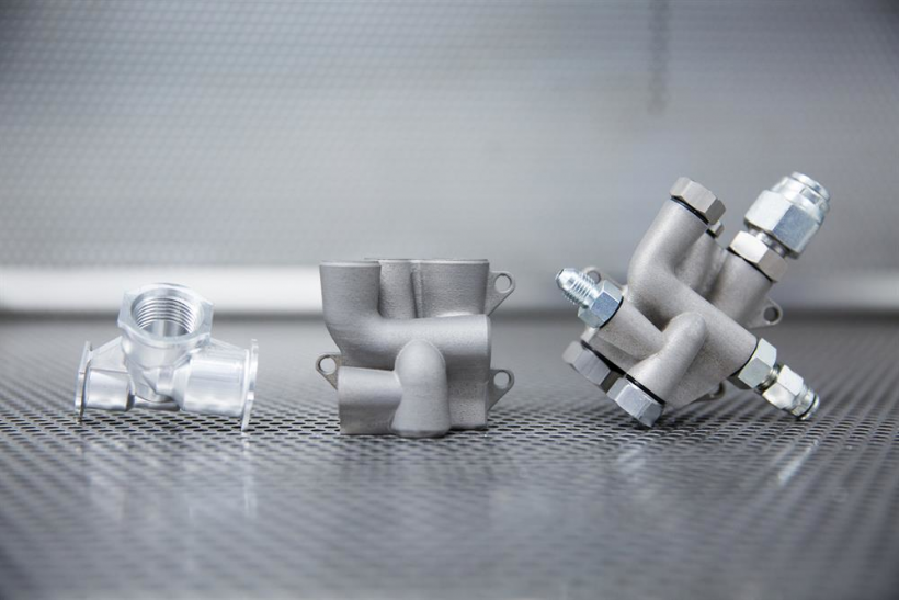
Take a hydraulic manifold as an example. This part, which helps to regulate fluid flow between the components of a hydraulic system, is typically machined from a solid block of metal.
Removing more excess metal than necessary is expensive, and, frequently, the excess metal is not machined away, resulting in a part that weighs more than it potentially could.
3D printing helps to overcome this issue, since it requires almost the same amount of material needed to produce a manifold.
In a metal 3D printing process, like Selective Laser Sintering, a laser traces a micron-thin cross-section of a part, selectively melting and fusing a metal powder layer by layer. This allows engineers to control the amount of material that goes into the part, using less metal than CNC machining would require.
In addition to reducing components’ weight, 3D printing also enables more compact parts that better fit into design-constrained spaces. This advantage makes 3D-printed hydraulic components particularly sought after in applications that require high precision and light weight.
Spotlight: Aidro’s 3D-printed manifold
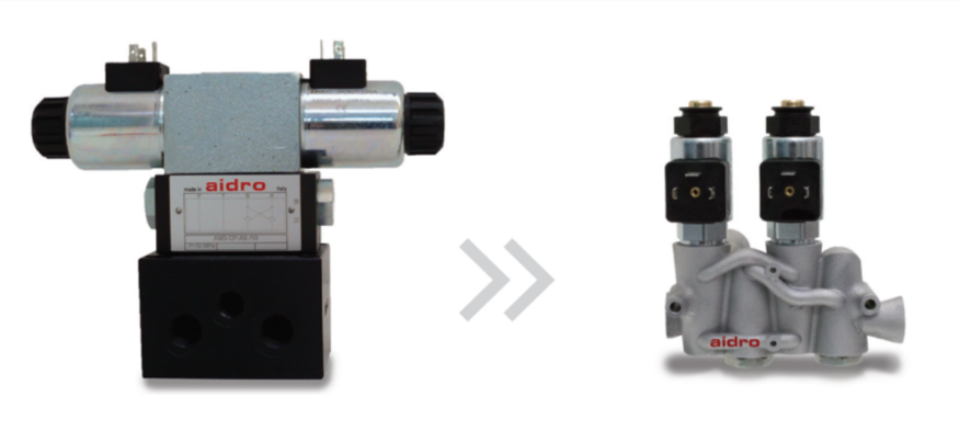
A 3D-printed manifold (on the right) is 75 per cent lighter than a conventional alternative (on the left) [Image credit: Aidro]
One example of a 3D-printed hydraulic component comes from Italian manufacturer, Aidro.
Aidro’s hydraulic manifold, used in agricultural machinery, was redesigned to save weight and space in a system it’s used in. The 3D-printed aluminium manifold performs the same functions as the unit it replaces but is half the size and 75 per cent lighter than the previous manifold.
Part consolidation
3D printing also allows components to be made smaller, by integrating multiple parts into one – an approach known as part consolidation.
This allows manufacturers to eliminate complex assemblies of components, as well as enhance the structural integrity of a part, since there are fewer weak joining points that can cause leakage.
Optimising efficiency
3D printing allows hydraulic components manufacturers to make parts lighter and smaller in size.3D printing makes it possible to redesign the internal geometries of a hydraulic component to optimise fluid flow and reduce pressure drop.
Taking manifolds as an example, engineers can position fluid flow channels inside a manifold precisely where they are needed and in a variety of shapes and sizes. This means flow channels can have curved shapes and be spaced closer together than with conventional manifolds, which makes the finished product more compact and lighter.
Curved flow paths can reportedly improve flow efficiency by 30 to 70 per cent.
Take a hydraulic manifold as an example. This part, which helps to regulate fluid flow between the components of a hydraulic system, is typically machined from a solid block of metal.
Removing more excess metal than necessary is expensive, and, frequently, the excess metal is not machined away, resulting in a part that weighs more than it potentially could.
3D printing helps to overcome this issue, since it requires almost the same amount of material needed to produce a manifold.
In a metal 3D printing process, like Selective Laser Sintering, a laser traces a micron-thin cross-section of a part, selectively melting and fusing a metal powder layer by layer. This allows engineers to control the amount of material that goes into the part, using less metal than CNC machining would require.
In addition to reducing components’ weight, 3D printing also enables more compact parts that better fit into design-constrained spaces. This advantage makes 3D-printed hydraulic components particularly sought after in applications that require high precision and light weight.
Spotlight: Aidro’s 3D-printed manifold

A valve spool with 3D-printed square holes (on the right) has a 20 per cent increase in flow capacity compared to the machined counterpart (on the left) [Image credit: Aidro]
Redesigning a shape of the cross-section of flow channels can also make a difference. For example, flow paths in valve spools typically have a round shape, because they are machined with rotating cutters.
3D printing allows engineers to design cross-sections of flow paths to be square instead of round, which can increase flow capacity by up to 20 per cent and reduce pressure drop.
Furthermore, traditional hydraulic components, like manifolds, often require machining of cross-drilled passages that must subsequently be plugged to prevent oil leakage. These plugged channels, however, create potential leak paths that can cause a system failure. 3D printing eliminates this issue, by removing the need to create cross-drilled passages in the first place.
More examples of 3D-printed hydraulic components
3D printing a hydraulic adapter block
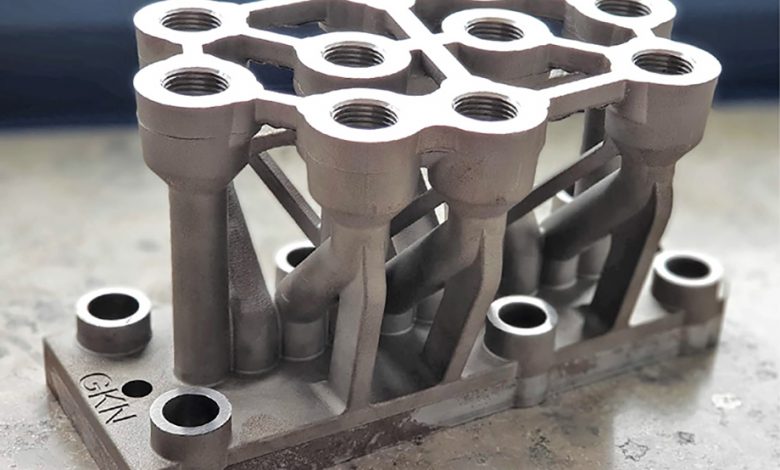
[Image credit: GKN Additive]
GKN Additive has 3D printed a hydraulic adapter block, which is a manifold that directs the flow of fluid in a hydraulic system, linking valves, pumps and actuators.
Traditionally used hydraulic blocks tend to have a blocky design with a set of internal channels drilled into them. The process of manufacturing hydraulic blocks starts by drilling holes from above and below.
The vertical holes are then connected by horizontal channels, and the threads are cut into them. To prevent oil leakage from the open horizontal channels, they are plugged with grub screws and sealed off.
This process, however, is highly inefficient for several reasons. Firstly, the drilled and milled edges create sharp burrs that are difficult to reach in post-processing. These can sometimes break off during operation and cause a system failure.
Secondly, the sharp corner connection points generate turbulent flow, resulting in energy inefficiencies. Thirdly, unused horizontal channels can accumulate dirt, lowering the operational life of the hydraulic system.
3D printing helped GKN Additive overcome the above challenges to create a better performing hydraulic block.
The weight of the hydraulic block was reduced from 30 kg down to 5.5 kg, without sacrificing any of the functionality. With a new design, it was possible to get rid of the excess material and ensure there were no bore overlaps within the part.
Furthermore, the new design omits the unused horizontal channels altogether, so dirt has nowhere to accumulate. Finally, to reduce the turbulent flow in the system, engineers replaced sharp internal corners with smooth pipelines.
Summing up the benefits of 3D printing for this application, 3D printing enabled the manufacturer to improve the component’s functionality, while using less material. This translated into lower weight of the part and reduced cost of manufacturing.
Liebherr’s 3D-printed hydraulic valve block
[Image credit: Liebherr]
Another good example of 3D printing for hydraulics comes from the Liebherr Group. With the help of 3D printing, the company was able to redesign a high-pressure hydraulic valve block, used in aircraft, to make it lighter and more efficient.
The Liebherr team integrated 10 functional elements into the new valve block, eliminating the complex system of pipework with lots of transverse bores. The result is a 35 per cent lighter valve block, made from fewer parts.
The 3D-printed part has been successfully tested in a test flight of the A380 aircraft.
Domin Fluid Power reimagines its fluid power systems with 3D printing

Ford 3D prints an intake manifold
While we’ve seen the examples of hydraulic components 3D printed for heavy equipment and aircraft, Ford has been pioneering 3D printing for automotive hydraulic systems.
Last year, the automaker showcased what it claims to be the largest 3D-printed metal intake manifold ever put inside a working vehicle.
That vehicle is Ken Block’s ‘Hoonitruck’ Ford pickup.
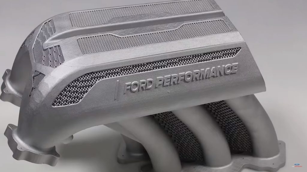
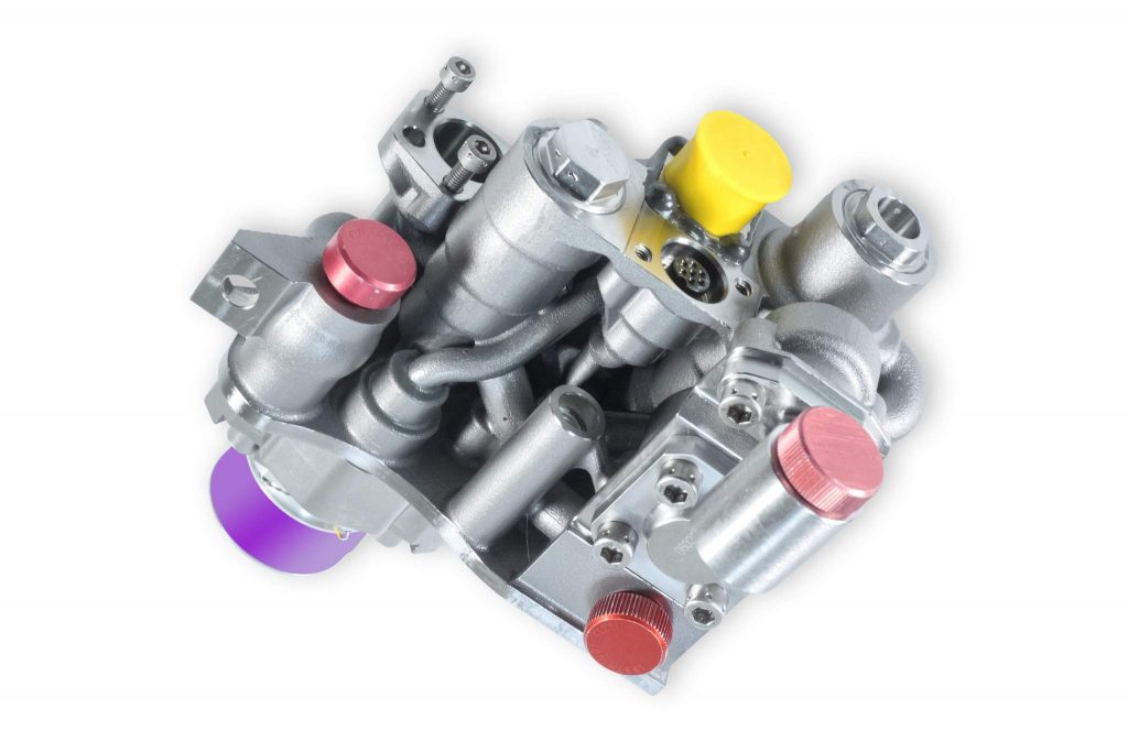
[Image credit: Ford Performance]
The vehicle required a special intake manifold to supply the engine’s cylinders with air from the turbochargers, and Ford decided to turn to metal 3D printing.
The part is 3D printed from aluminium, using a Concept Laser machine, and took 5 days to build. By using cutting-edge CAD software, it was possible to create a complex web‑like structure that couldn’t be made using traditional manufacturing methods. The design is optimised for better performance and lower weight – the final part weighs just 6 kg.
Bosch Rexroth uses sand 3D printing for manifolds
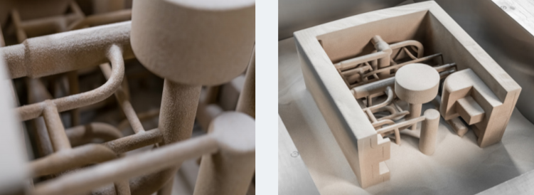
[Image credit: Bosch Rexroth]
In addition to metal 3D printing, there’s also an option of 3D printing a sand core that can subsequently be used to cast a hydraulic component. The process used for this application is called binder jetting, and it works by selectively depositing a binding agent on a layer of silica sand.
Bosch Rexroth has been using sand 3D printing for producing cast cores for control blocks, for several years now.
Among the key benefits of doing this, Bosch Rexroth names the ability to integrate machine components, such as filters in the manifold, and weight reduction by up to 30 per cent.
Additional benefits include the eliminated need for auxiliary holes that can cause leaks and optimisation of internal flow channels that improve energy efficiency.